By: Ryan Ollenburger, Sr. Solution Architect, Dasher Technologies
Overview:
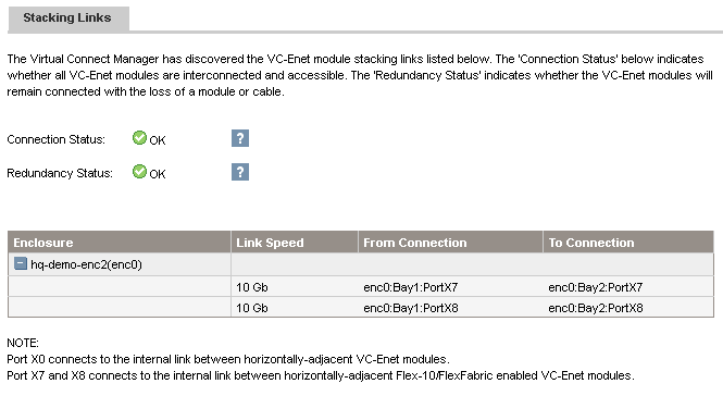
Virtual Connect FlexFabric is the first Data Center Bridging (DCB) and Fiber Channel over Ethernet (FCoE) solution introduced into the HP BladeSystem portfolio. FlexFabric provides a converged way of connecting to any data or storage network over a single device, eliminating multiple edge devices. Each FlexFabric module provides 24 line-rate 10Gb ports for a total of 240Gbps switching capability. As shown in figure 1, there are 8 faceplate ports. Ports X1-X4 can accept a 10Gb Ethernet or 8Gb Fiber Channel SFP+ transceivers. Ports X5-X8 are SFP and SFP+ capable, and can support 10Gb or 1Gb (RJ45) Ethernet transceivers.
Image 1: HP Virtual Connect FlexFabric Module
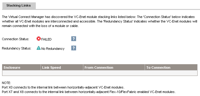
Ports X7 and X8 are shared with an internal stacking link ports. Stacking links provide an inter-module path for networks to an active uplink (active/standby uplink configuration). They also provide a path for internal networks that do not belong to an uplink set. These are most common in environments where outside connectivity is not required (cluster networks, heart-beat networks, etc.). Image 2 is a screenshot of the typical stacking link between modules as displayed in Virtual Connect Manager.
Image 2: Virtual Connect Manager stacking links active
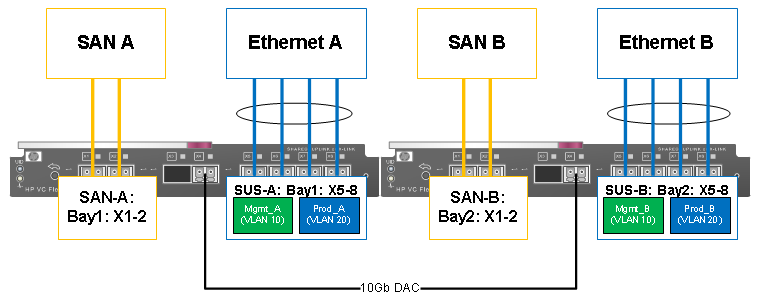
 If port X7 and X8 are populated with a transceiver, the internal stacking links are disabled and Ethernet networks do not have a path between modules. Stacking errors are also displayed in Virtual Connect Manager as seen in image 3.
Image 3: Virtual Connect Manager stacking link errors
 At least one stacking link is recommended to provide an inter-module path for Ethernet networks as well as avoiding errors in Virtual Connect Manager.
Common uplink configurations and how they affect stacking links:
For environments that have 10Gb connectivity available upstream, we commonly configure 2 8Gb fiber channel uplinks for SAN connectivity and 2 10Gb uplinks for Ethernet connectivity, per FlexFabric module. As seen in image 4, this configuration does not require the use of port X7 or X8 and the 2 internal stacking links between the modules are fully operational, allowing a path for Ethernet traffic between modules.
Image 4: 10Gb Uplink Configuration
 In environments that do not yet have 1OGb connectivity available upstream, it’s common practice to aggregate multiple 1Gb ports for use as uplinks. Since only ports X5-X8 support 1Gb Ethernet uplinks, we usually use all of them to provide a reasonable amount of bandwidth to the enclosure. Image 5 depicts this configuration.
Image 5: 1Gb Uplink Configuration
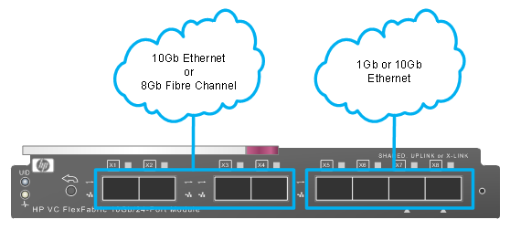
By using ports X7 and X8 for 1Gb uplinks, the internal stacking links are disabled, causing stacking link errors in Virtual Connect Manager as well as no path for internal networks between modules. To overcome this issue, we can simply add an external stacking cable as shown in image 6.
Image 6: External Stacking Link
By using a short 10Gb direct attach copper (DAC) cable between any of the free ports in the FlexFabric modules, we can avoid stacking link errors from Virtual Connect Manager and provide a path between modules for Ethernet networks.
Summary:
To avoid stacking link errors in Virtual Connect Manager and provide an inter-module path for Ethernet networks, it is recommended to have at least one stacking link between Virtual Connect modules. By default, ports X7 and X8 provide this, but depending on uplink configuration, these may be disabled and external stacking cables may be necessary. The use of 10Gb DAC cables between free ports on the Virtual Connect modules will automatically be configured as stacking links and provide the inter-module connectivity we need.
(For more information about Virtual Connect FlexFabric, go to Virtual Connect)


